As I first reported in 2004 about my fix on Aristocraft.com,
if your Dash-9, E-8, SD40 (or other 3 axle Aristocraft
engine) runs choppy or seems to have a lot of gearbox noise, you may have one or
more motors binding due to the U shaped power transfer strips pushing them out
of alignment.
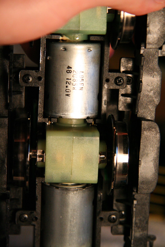
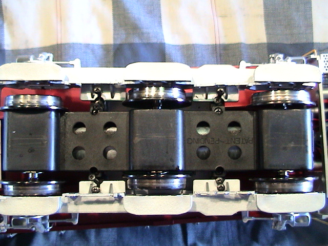
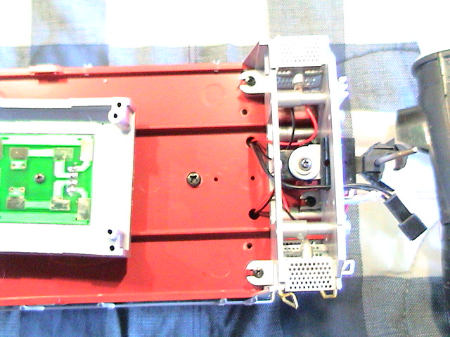
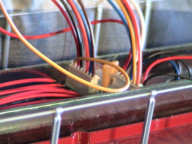
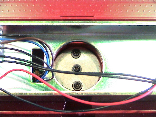
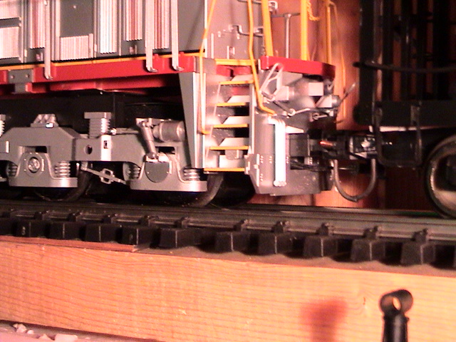
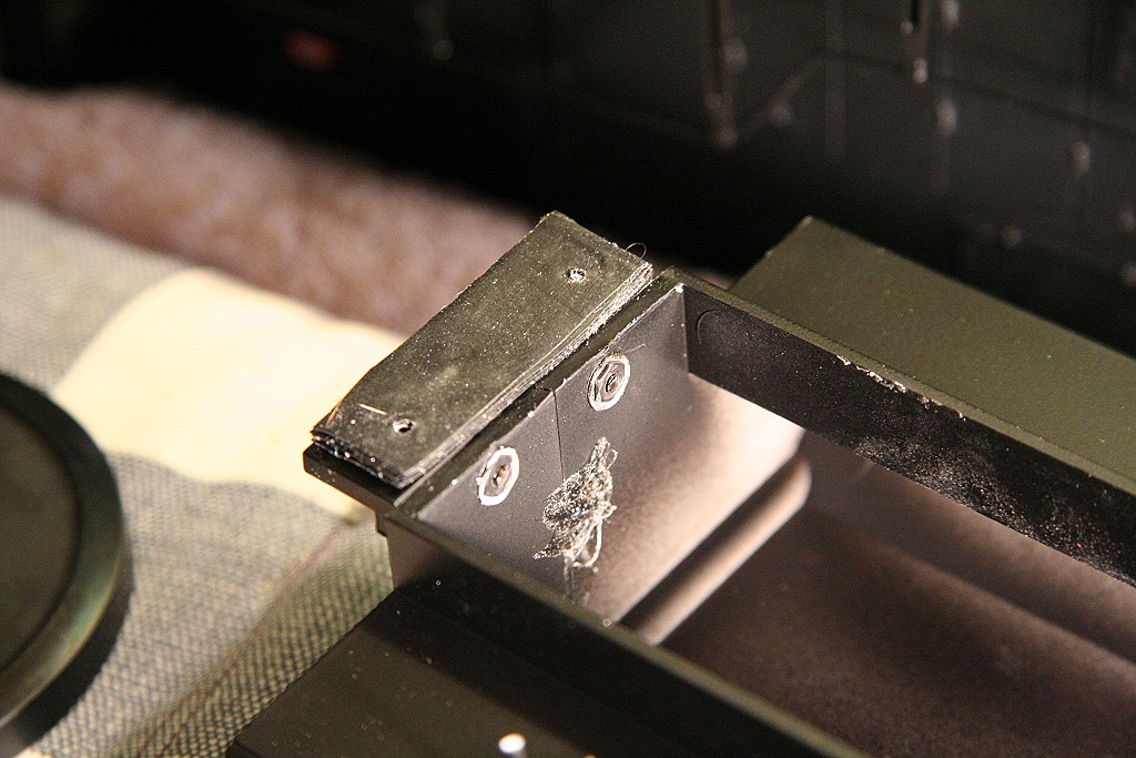
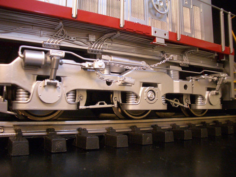
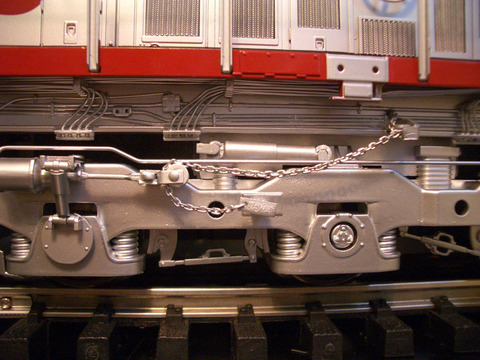
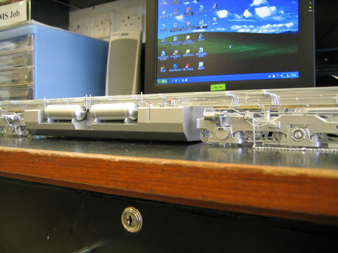
The U shaped power transfer strips that
route power from the top circuit board to the + and - motor power leads on the
motors can create downward pressure on the power lead side of the motors as the
strips are pushed down into the motor block as the block is screwed down to the
truck frame/bolster. This downward pressure forces the motor ends out of
alignment with the gearboxes and causes them to push/bind against the inside of
the inside of the gearbox worm gear.
INSTRUCTIONS ON HOW TO FIX:
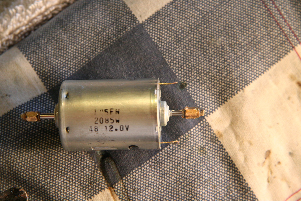
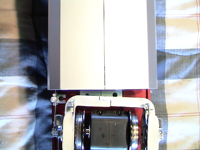
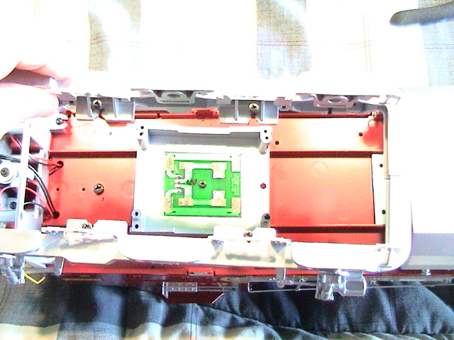
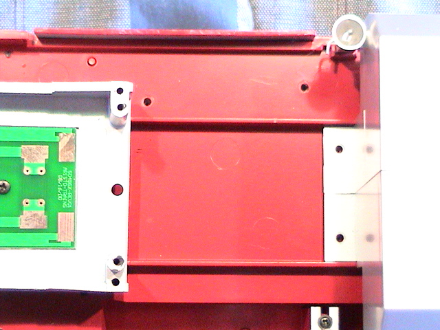
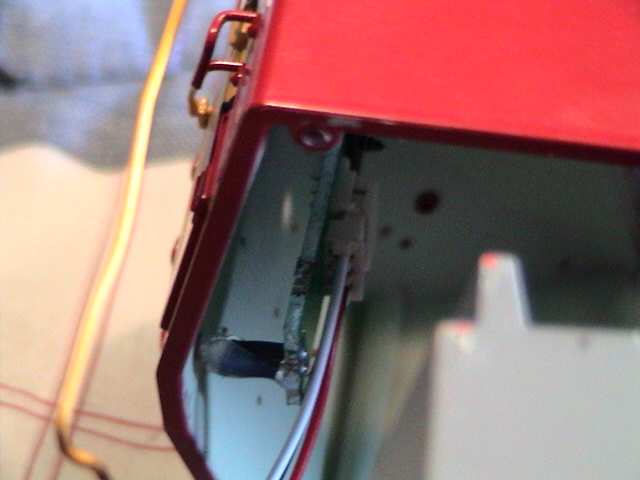
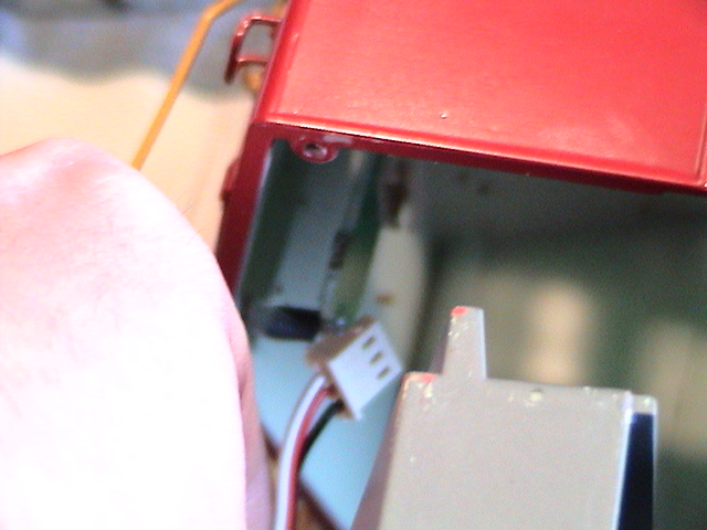
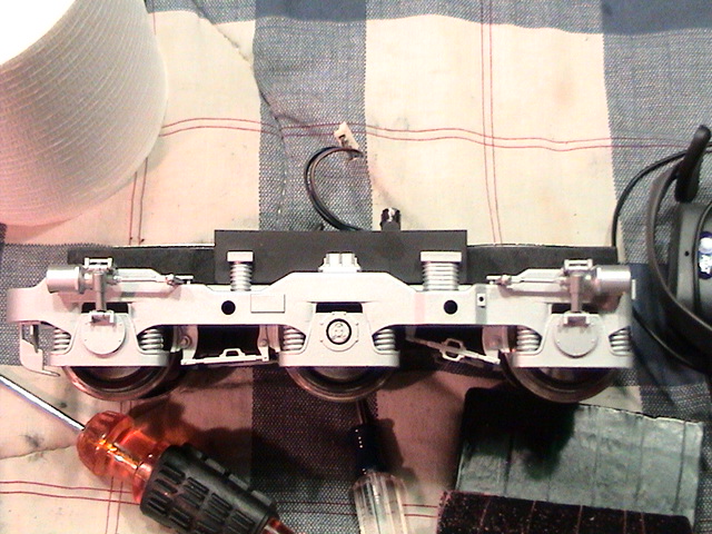
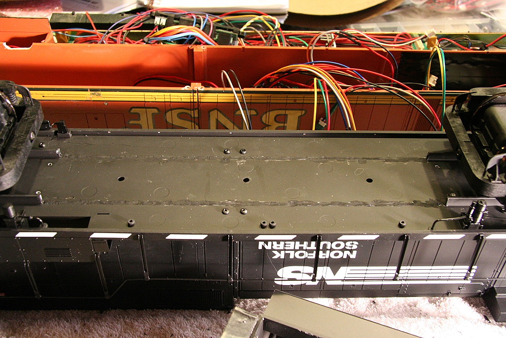
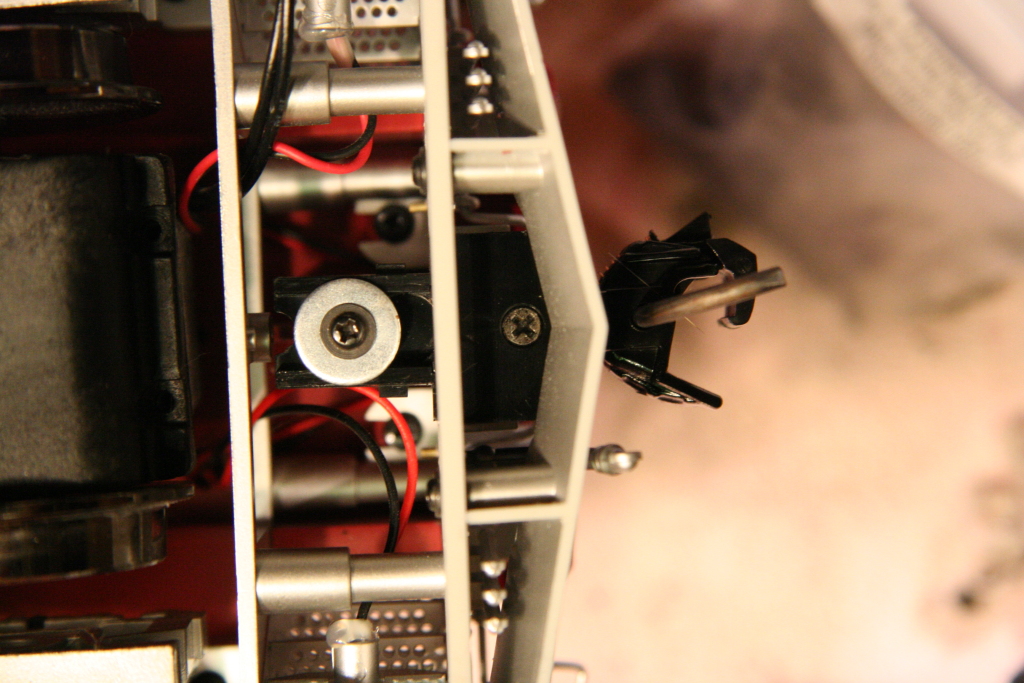
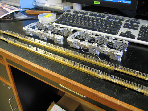
First, flip the engine upside down and
only remove the bottom shell casing of the motor block. DO NOT remove the motor
block from the engine. (note, mine in the photos below is out of the engine, but
is still installed in the truck frame and is solid against the circuit board
above which is the key to all this.)
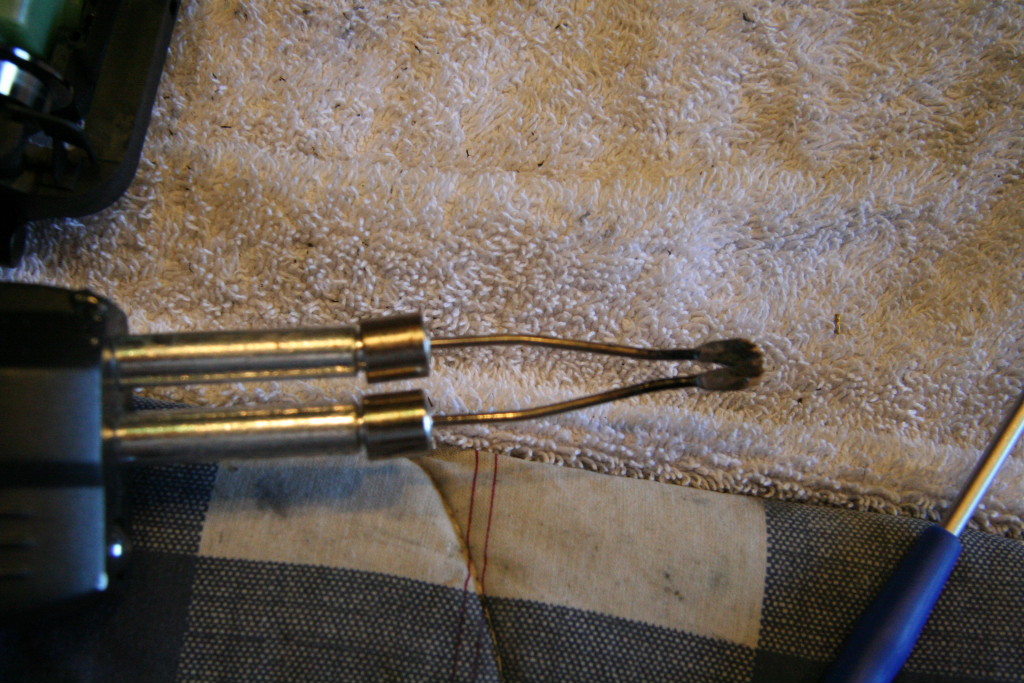
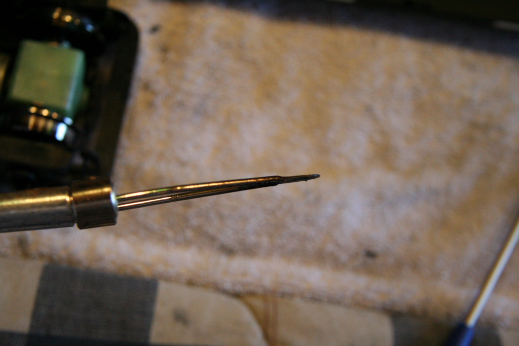
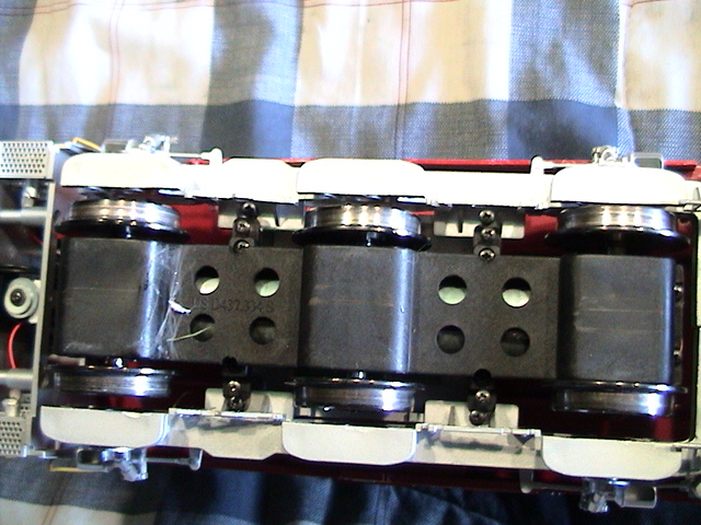
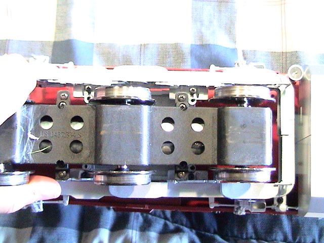
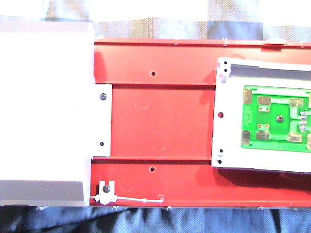
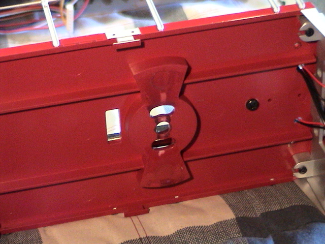
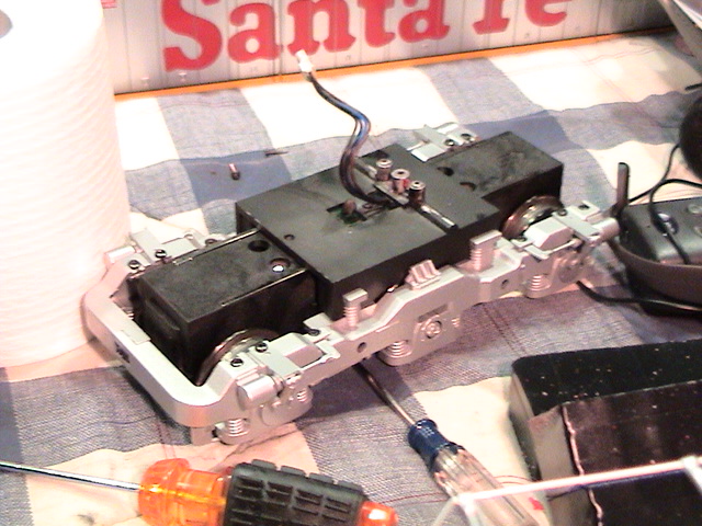
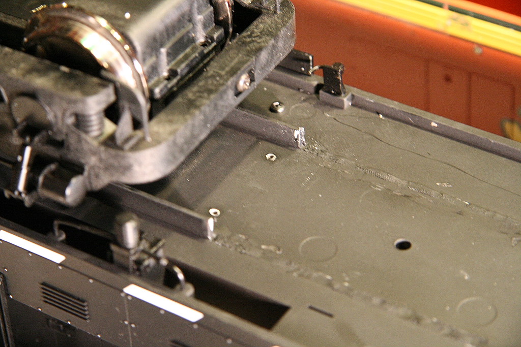
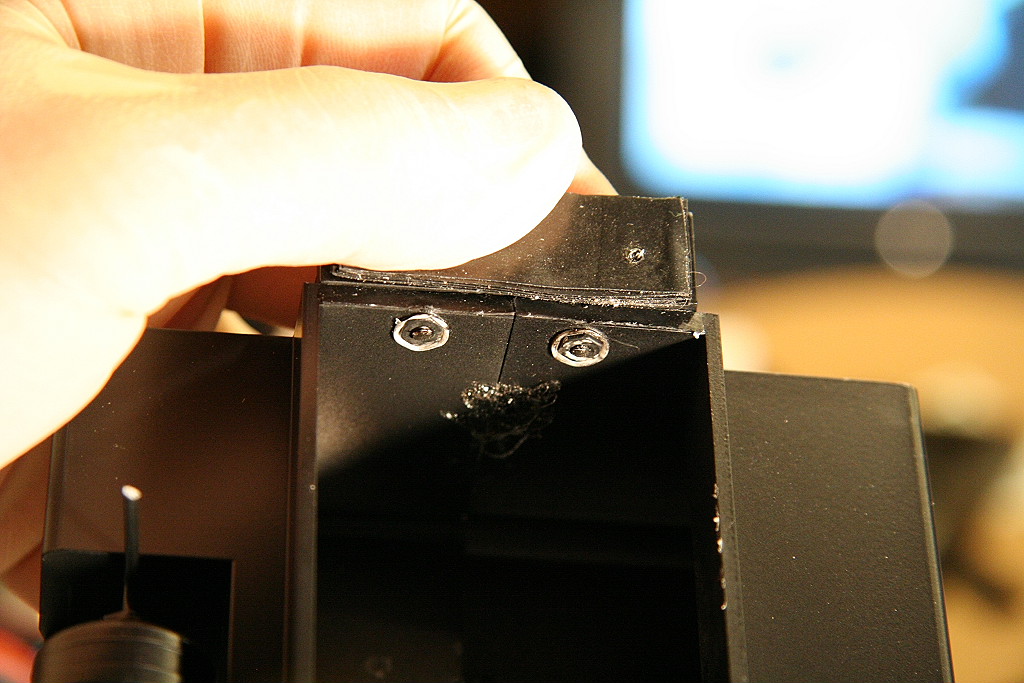
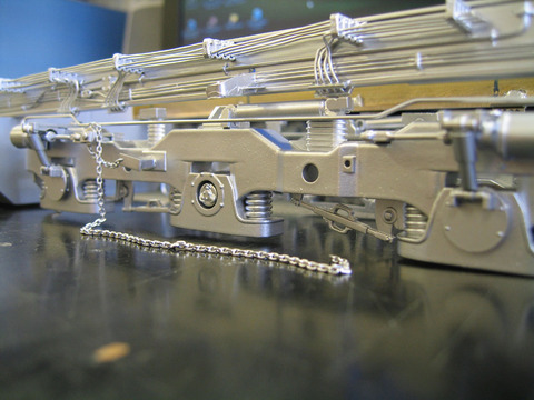
Simply use the soldering iron with this type of tip till you soften the solder
on each terminal. Be sure to apply some pressure down on the tab of motor block
power lead to push it back into place.
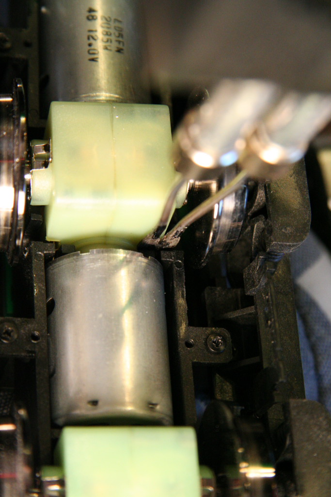
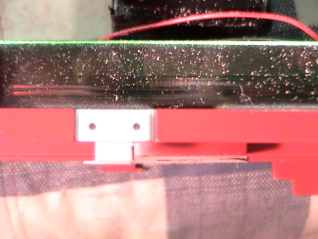
Here is a video to illustrate the before and after results. It shows how
the stress on the end of the motor from the U power strips is negatively
impacting the motor driveline alignment.
Notice the center gear box movement before and after the solder is loosened.
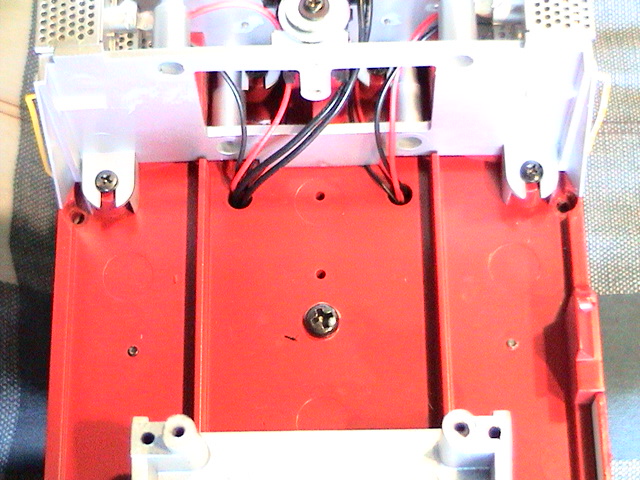
The root cause of the problem is likely
due to the fact the motor blocks are assembled outside of the engine (as opposed
to installed in the engine) at the factory, then installed afterwards. If
the U shaped power transfer strips are not perfectly tight down against the top
of the motor block they will be pushed down into the block (as it's pressed
against the above power transfer circuit board) causing the out of alignment
problem with the motors which results in binding and noisy operation.
Please note: If your engine
exhibits this problem it will not get better by trying to run it to break it in.
The root problem needs to be fixed in order for the symptoms to go away.
If you get a good
amount of run time on your engine you may encounter this issue where either a
gearbox fails or the entire drive-train fails to operate.
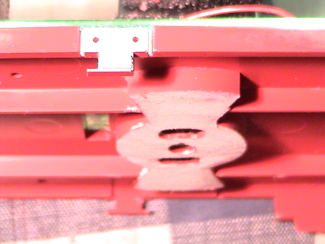
The failure will be
because the plastic axle gear
or plastic worm gear strips in one or more of the gearboxes. If this
occurs that drive-wheel will no longer spin with the rest of
the wheels.
If this happens to
your engine, you
will need to to either replace the gearbox or send the drive-train in to
Aristocraft for replacement. Aristocraft engines have a 5 year warranty
and will replace it for free if still under warranty.
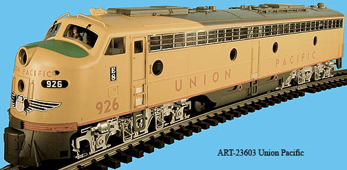
Example of drive
train/gearbox failure on an E-8: (Same motor block as Dash-9 & SD45)
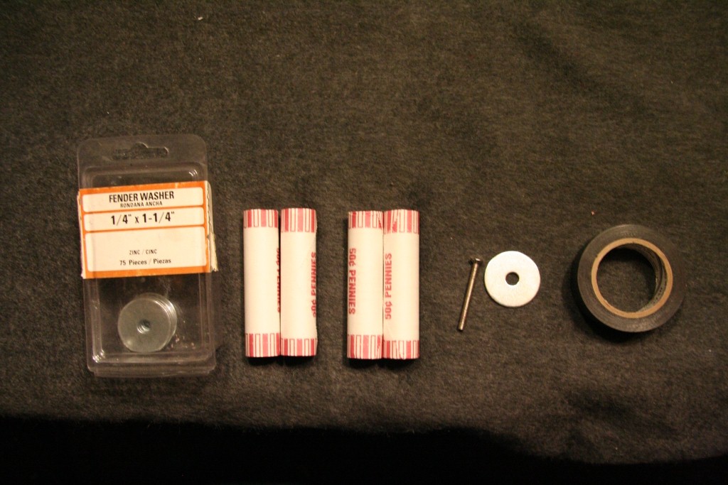
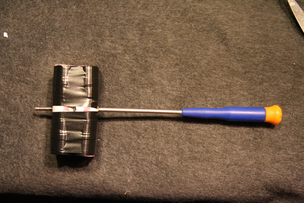
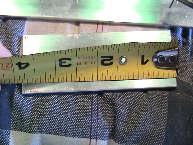
Instead of paying $42.00 (MSRP- ART29514) for a pair of 1lb weights (which used
to be free), I've decided to make my own for about $2.00 each. (weights ~1lb
3oz)
Screws if you
need them can be purchased from Ace Hardware and are a 4mm screw with a .70
thread pitch.
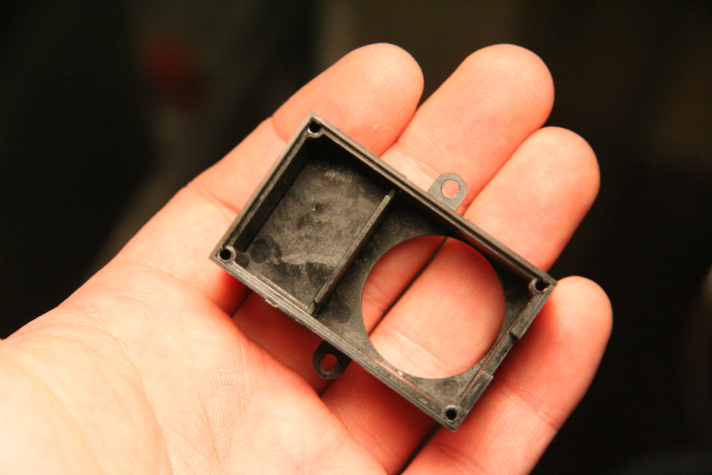
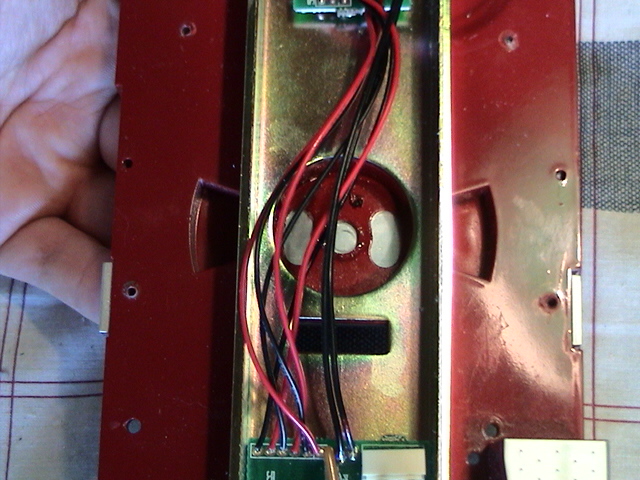
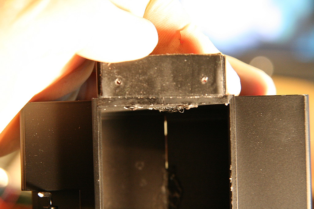
Sealing the Aristocraft smoke unit fluid reservoir tank
to prevent leaks:
I've found most of the Aristocraft smoke units leak around the inside wall when
fluid is added. To keep this from happening, I run a bead of superglue
along the outside corner of the inside wall to seal it. Once sealed it
won't leak anymore. I usually let it sit overnight to fully dry before
reassembling.
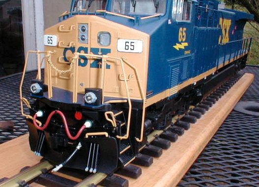
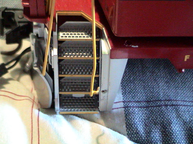
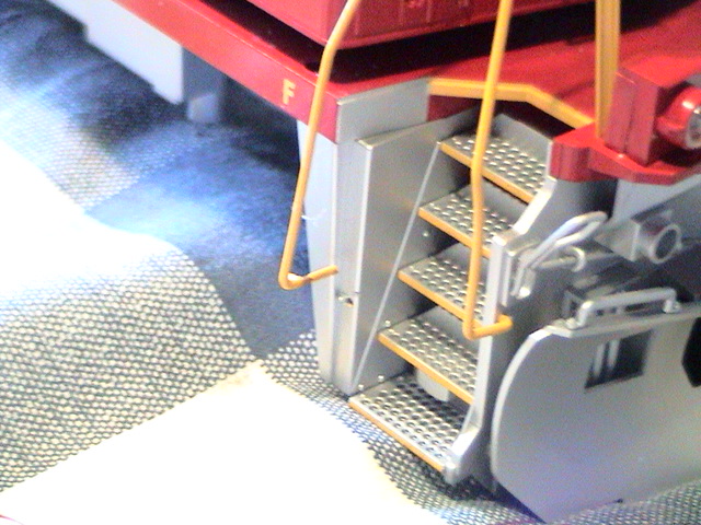
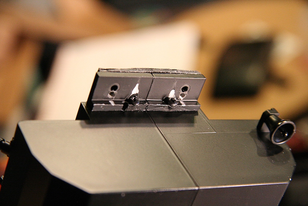
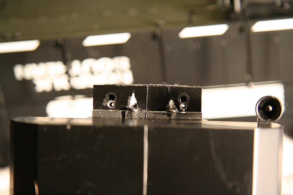
As you may
have found yourself, the holes for the front and rear handrails are drilled too
small and as a result you either can't get them in the holes or can't get them
to stay. To resolve, I used a .052 inch drill bit and drilled out the hole
(by hand, not with a drill). Each hole may require a bit more working
depending on the particular end you're trying to fit in. To gain access to
drill out the front holes, just remove the plow by removing the two screws on
the backside.
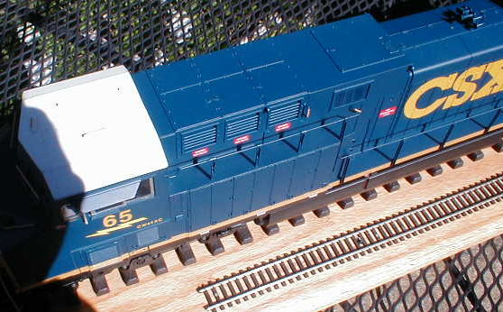
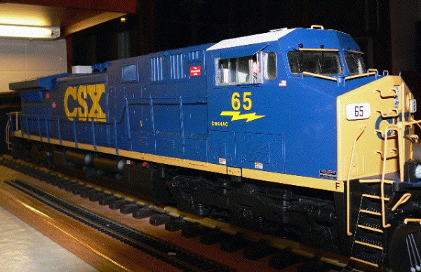
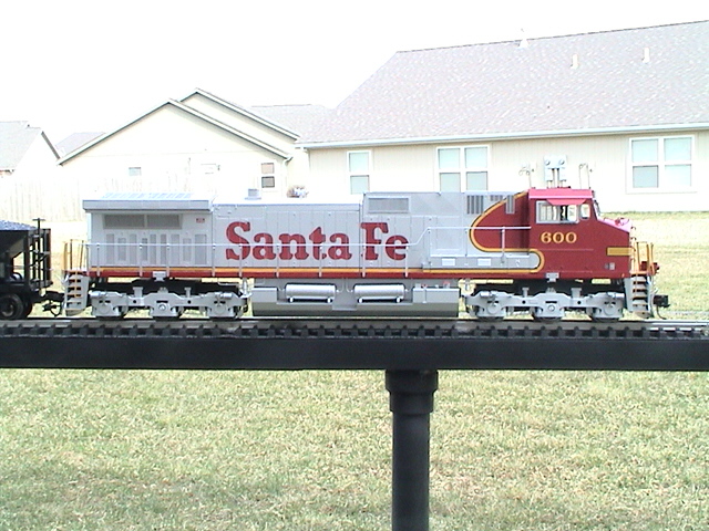
After seeing pictures of this Dash-9 that was
lowered, I decided I'd like mine to be a bit lower than it was. The below
pics of the CSX model were taken by Paul R who modified the engine.
Needless to say Paul did an excellent job.
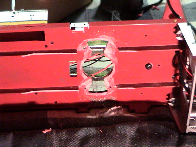
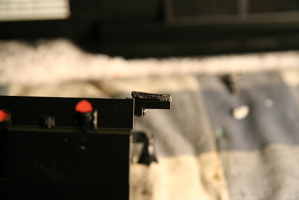
Stage 1: (1/8" lower)
I lowered my engine in two separate stages. The first is
shown in the first set of pictures where I simple sanded off 1/8" of the surface
where the trucks ride on the frame. I wanted to go further but it would
have required replacement of
the platform with a sheet of metal. (which is what Paul R did on his) Here
are some of the pictures at various stages of disassembly.
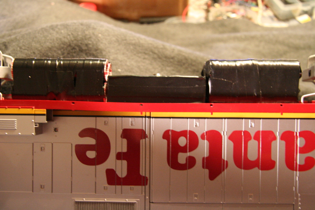
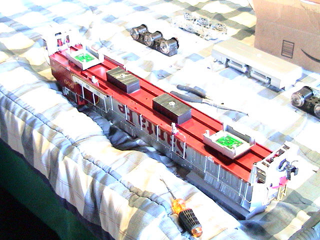
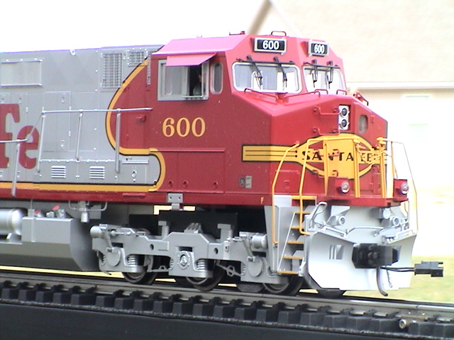
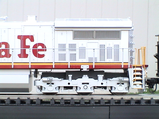
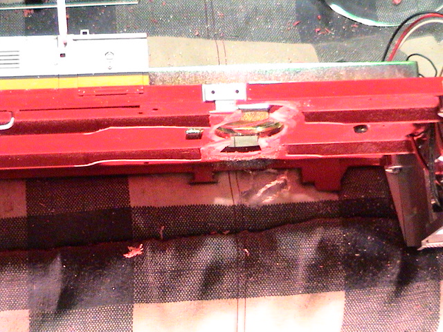
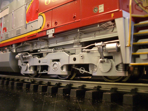
Here is what it looks like after it was lowered the 1/8" and the
truck boxes above the motor blocks painted black. The work was easy to do
and made it look a lot better in my opinion.
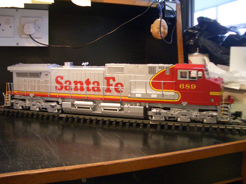
Below are some comparison pictures of what it looked like before
lowering.
03/18/05
Stage 2: (the full .20" lower *approx*)
I decided to finish lowering it the rest of the way,
approximately another 1/8" for an approx total of .20". Everything has been completed except raising the
fuel tank. I will raise it but only slightly as I like the look of it hung
lower.
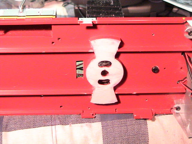
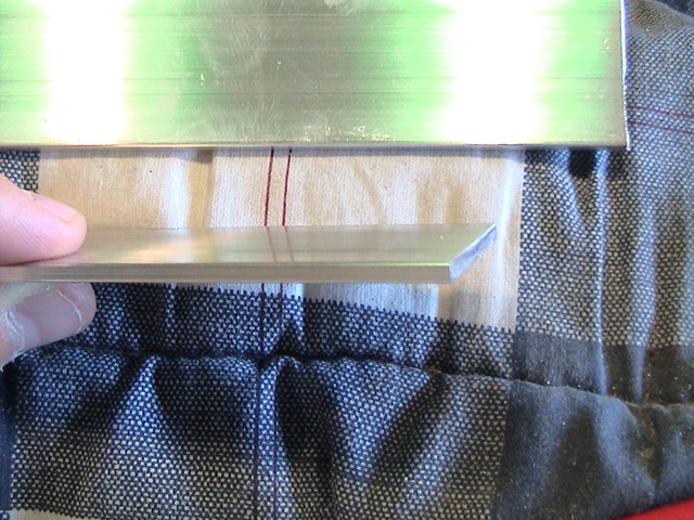
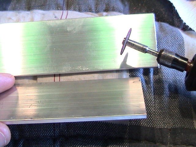
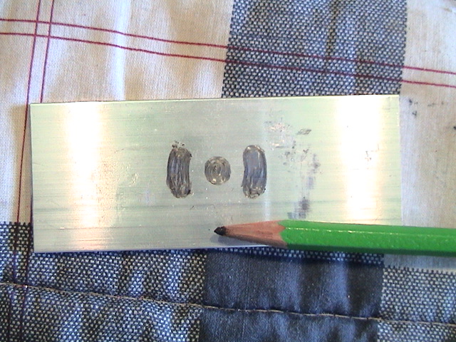
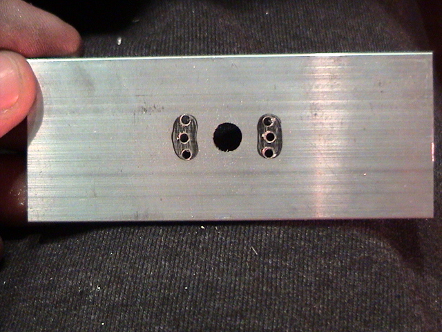
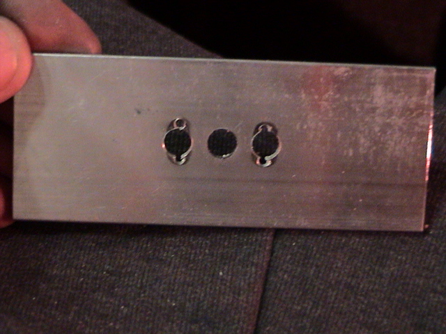
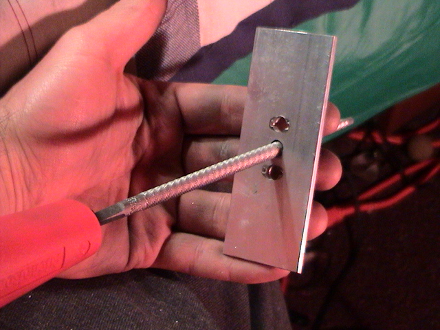
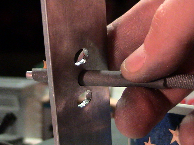
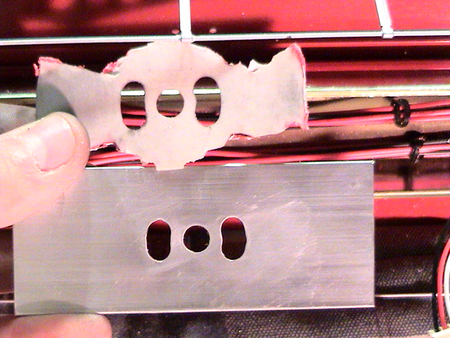
Here is the final method I used to drill the plates and the
slots. Using the original surface's holes and slots, I centered the
pattern on the plate and drilled three small holes for each slot and one larger
one in the center. I then used the same large bit to drill a hole in
the center of each of the glide slots with the already small hole as a guide to
keep the bit from wandering and to get perfect placement of the hole. I
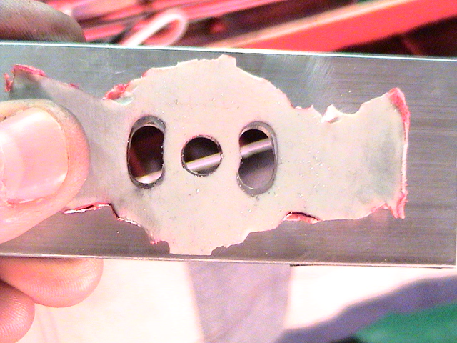
then used a proper sized round file to file out each side slot in the same shape
and size as the original. This was done by constantly comparing the
template to the plate and test fitting and pivoting on the trucks. After
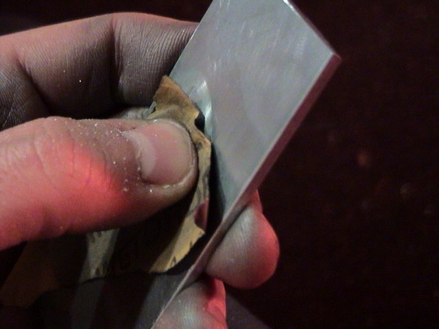
the holes were of proper size, I lightly sanded the surface with 1500 grit sand
paper to polish and smooth the surface. Next, the edges of the holes were
dulled by lightly sanding with my thumb pressed in the hole. Next, a strip
of 1500 grit sand paper was wrapped around the file and the inside of the holes
was sanded smooth to reduce wear on the truck pegs.
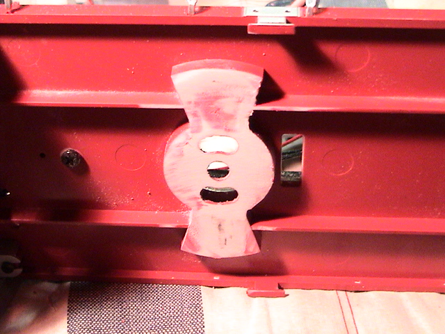
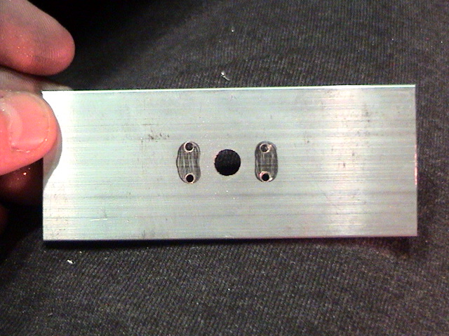
Note: The center hole in this case was drilled to a
perfect fit with enough rounding of the edges to allow the plate to rock in all
directions. No lateral movement front to back or side to side was allowed
for. This should limit the contact of the truck frames against the tank
and front and rear frames when the trucks twist around corners. Also note
that the slots were not filed out as long as the original, this again was to
limit the distance the trucks could twist. I intend to run 10ft curves at
a minimum and since the engine was designed for 8ft, I figured it could be
limited and still run the 10ft corners I had. Tests proved my thoughts
correct.
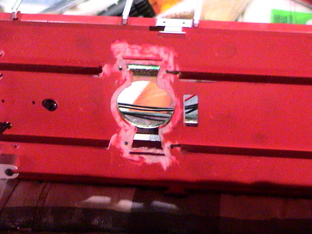
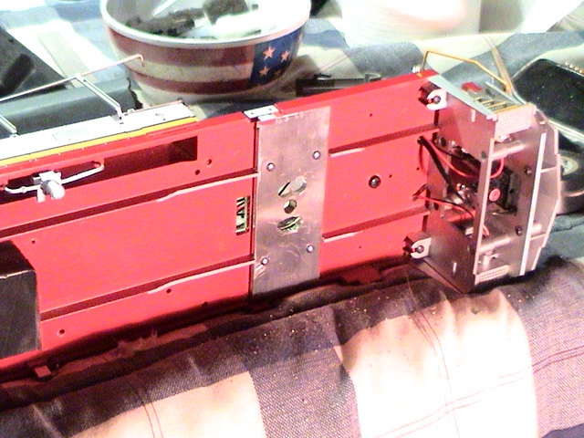
Below are picture of how the plates look installed. These
pics are with the first set of plates I made.
To secure the plates to the frame I mounted the plates in
place and drilled four holes through the plate and frame. #2 Stainless Steel
bolts and nuts (from Lowes) were used. To get the plates properly centered, I
put the plate in place, installed the truck in the slots then from the top of
the frame twisted the plate clockwise or counter clockwise and slid it around to
get the proper orientation. Next I then screwed the big washer in place that
holds the truck to the plate and further centered it so it was perfectly
centered. Next, I then applied hot glue in the exposed 'swing' areas where the
plate was now exposed and let dry. This freezes the plate in place so you can
drill the four holes for the permanent screws without the plate sliding around
or getting out of position.
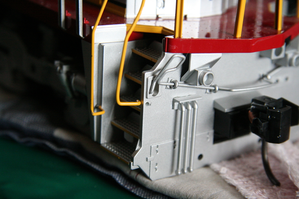
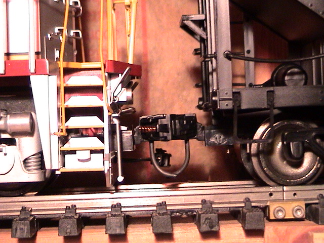
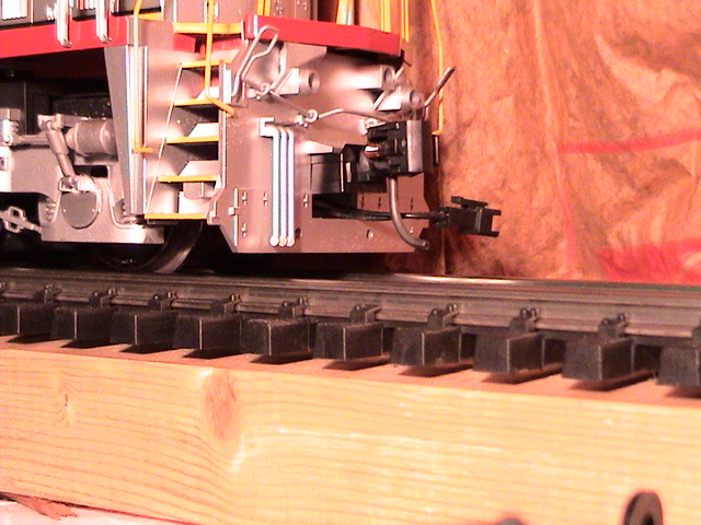
Here are the pictures of it reassembled with the new 787 Kadee coupler
(a combination of the 836 knuckle and 789 box) that
compensates for the new lowered stance. The front plow and front and rear
pilots were sanded down a bit with a block sander to allow more space between them and the rail.
To install the 787 coupler, I installed the coupler upside down
in the Kadee coupler box, drilled out the main Kadee coupler hole and installed
it over the existing Aristocraft coupler post. I then used a slightly
larger washer with the original screw to secure the coupler in place.
Kadee coupler install info is below.
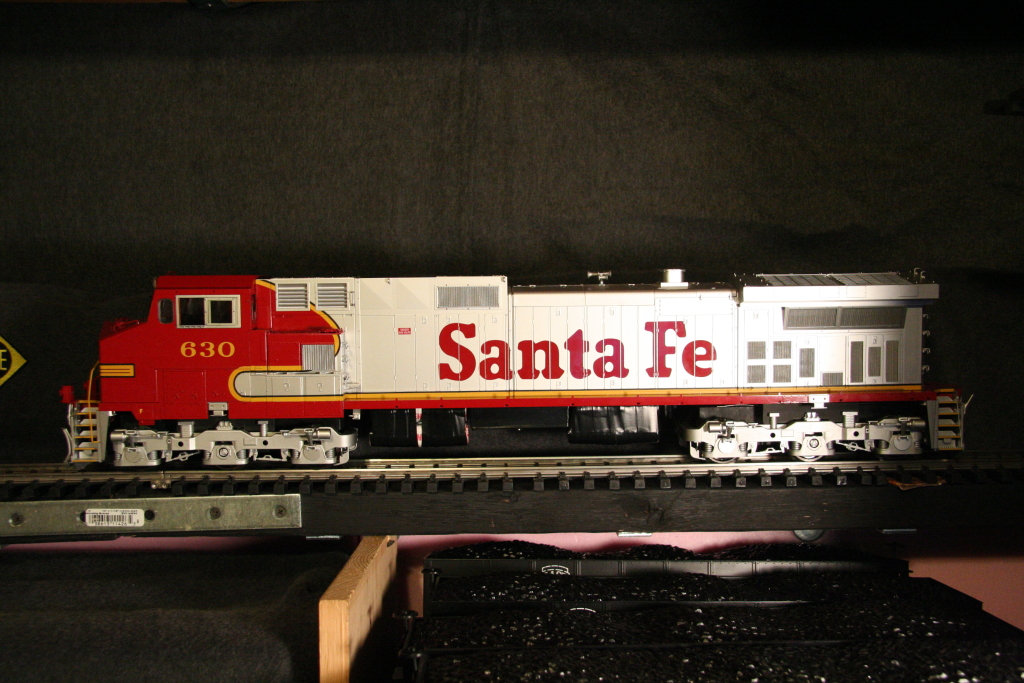
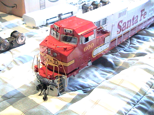
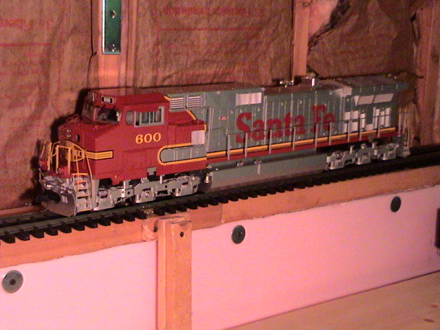
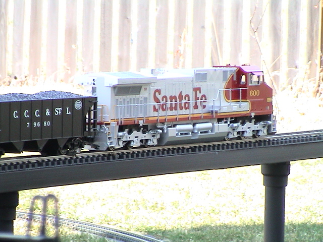
And here it is....
Overall lowering the engine
has made this great looking engine even better.
01/03/08
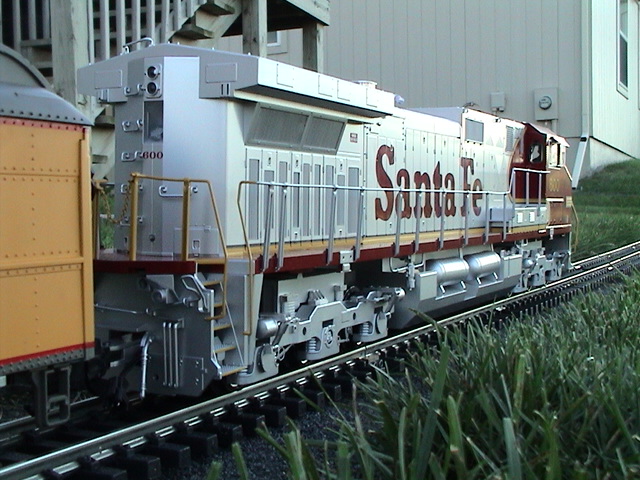
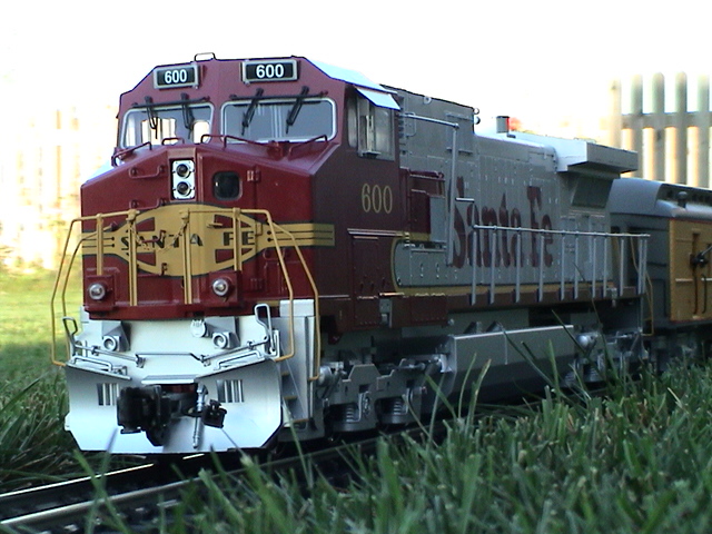
*Completed* Dash-9 with tank raised
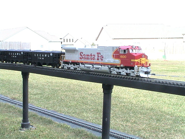
Below are a series of photos showing two different engines. (both
lowered .20") One has the tank raised ~.16" and the other is in it's
original position.
For reference, here are examples of the real thing:
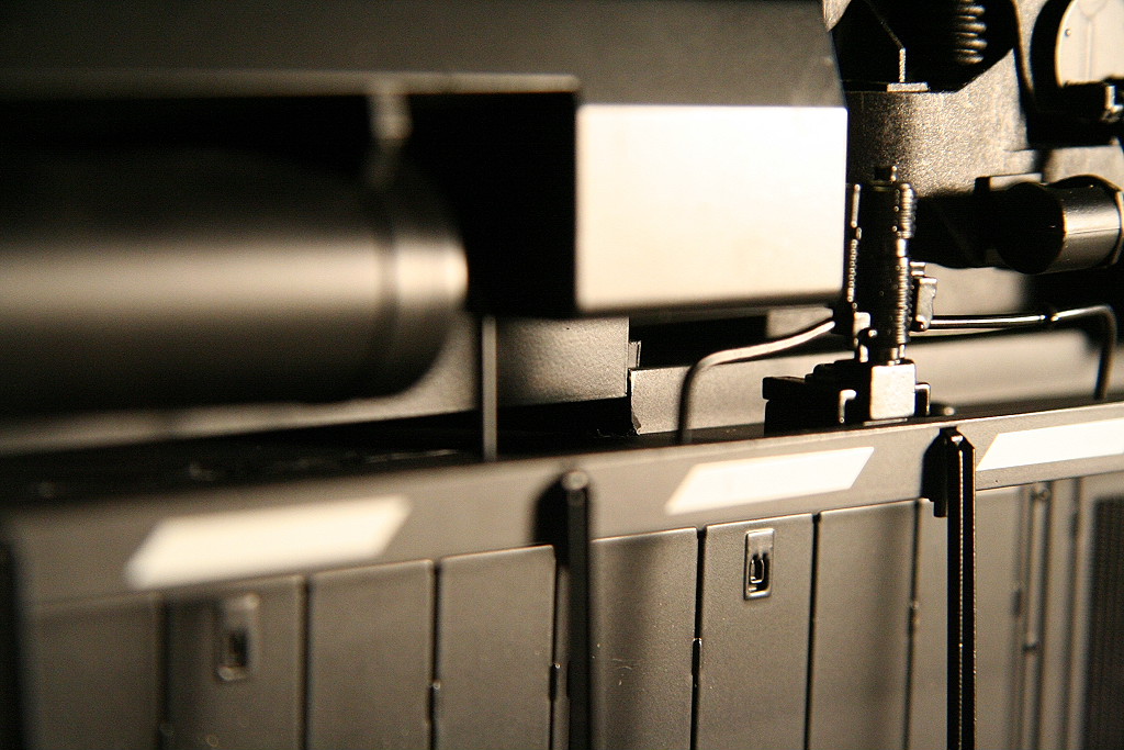
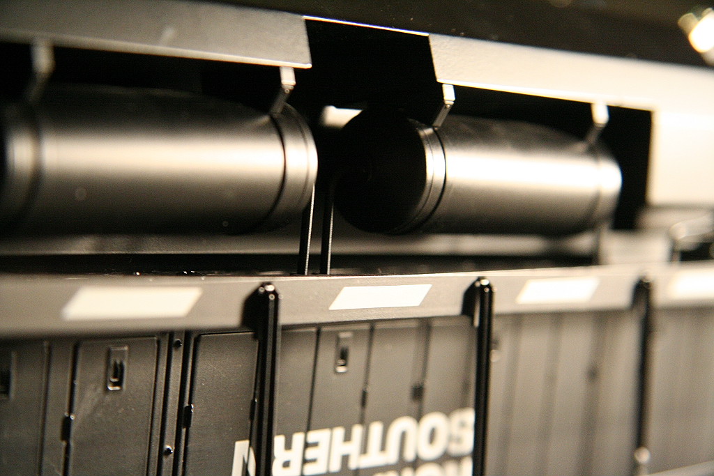
Here are photos that show the steps I took to raise the tank.
I cut out the raised portion of the frame, then cut the tabs off the tank with a
modelers cutter. The tabs were moved to the outside of the tank and were
bolted in place with 2-56 size screws and nuts. I then ground the excess
of the 2-56 screw on the inside of the tank which and the added benefit of
heating them which allowed them to melt and recess into the inside of the tank.
The recessing was necessary in order for it to clear the weights inside.
All cut areas were painted with Tamiya Acrylic flat black paint (XF-1). If
you mount the cut tabs at the right height, you won't need to shim or add
spacers to get the tank to the proper position. (the tank may be too high
depending on where you've mounted them.) If you need to adjust the height
lower, you can use something simple like electrical tape
to space it back down to the desired height. Also note the air tank pipes
must be clipped in order to allow the tank to be raised. Also, because the
tank tabs were moved to the outside of the tank, new holes have to be drilled in
order to screw the tank to the frame. You may need to use a longer screw
to retain the tank to the frame if you've added enough spacer to lower the tank. Because the
tank isn't raised all the way to the bottom of the frame, there will be a space
between the top of the tank and the frame. You really can't see it unless
you look hard and at ground level. To hide the weights you can either
paint the weights black where they are exposed or wrap with electrical tape.
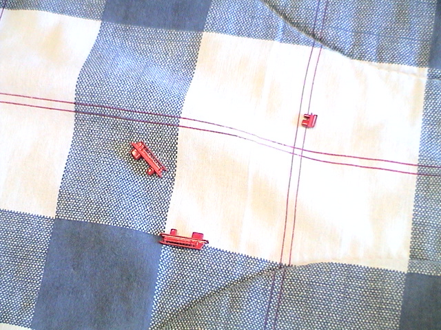
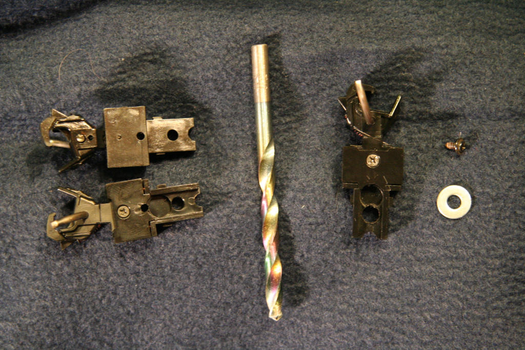
Kadee Coupler install
If you lower your engine, you will need to use an offset Kadee
coupler in order to achieve proper coupling. In the photos below you will
see the original screw + #8 washer and two unmodified 787 Kadee couplers and one
on the right that has had the mounting hole enlarged with a 15/64 drill bit.
Simply install and use a #8 washer to secure.
07/31/05
Gary To's Dash 9
Gary To (from Hong Kong) posted a link to these pictures of his
outstanding work on his Dash-9. Discussion about can be found on
www.aristocraft.com under the
Kitbashers' forum under the thread name "My Dash9". Great work and thanks
for letting me share your pictures here. :)