07/26/08
Adding Light switch, Polyfuses and Inductors:
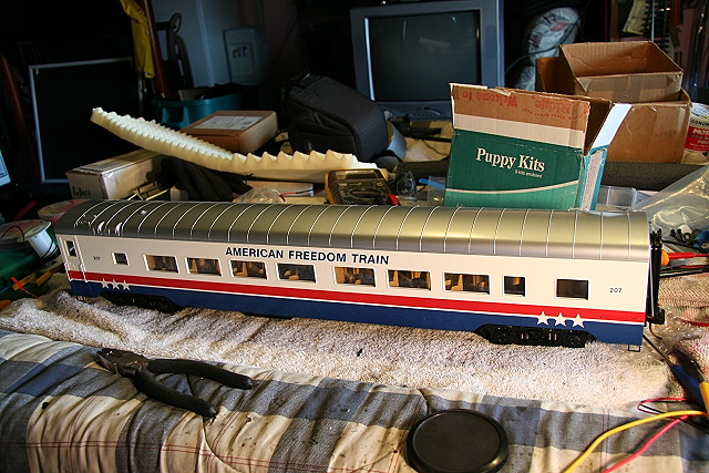
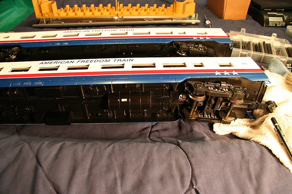
The MTH Passenger cars I purchased (American Freedom and
Daylight) were first production runs and did not come with on/off switches for
the lights as later runs did. Since I prefer to have the lights off during
the day I decided to add a light switch to each car and also add resettable
polyfuses to protect from accidental shorts that might occur. (see
http://www.rayman4449.com/Aristocraft_Heavyweight_Polyfuse.htm for
more info) In my case I also added inductors to the pos and neg wires to
eliminate the reductions in track signal on my digital control system.
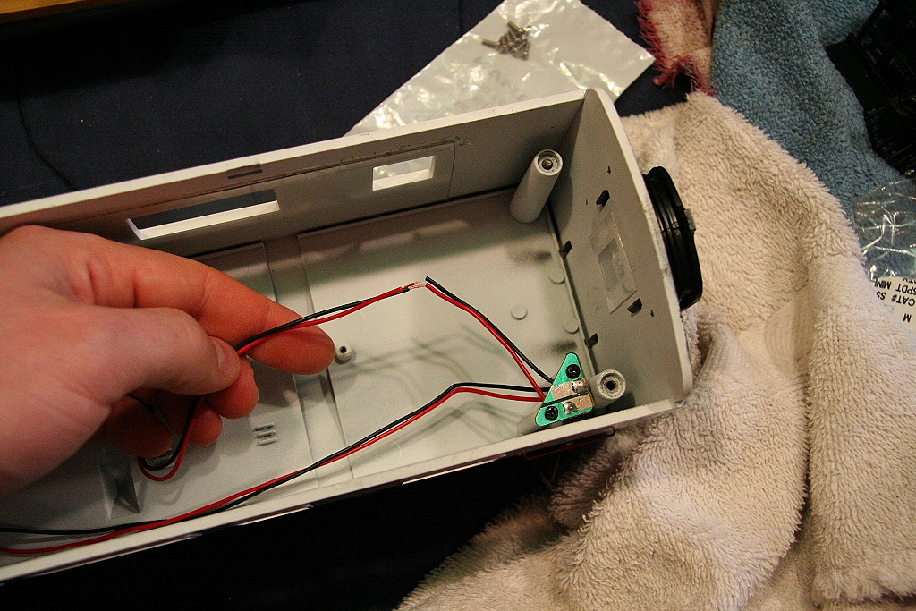
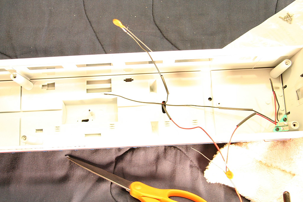
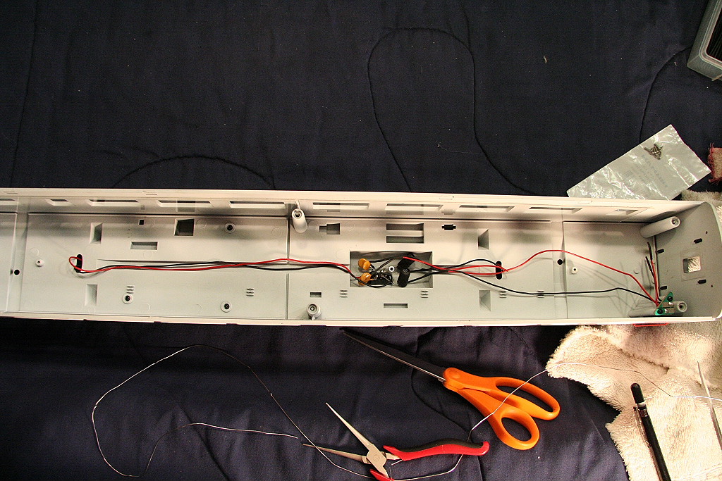
To start, I removed the top of the car by
removing the screws holding it down. (accessed through the bottom) I then
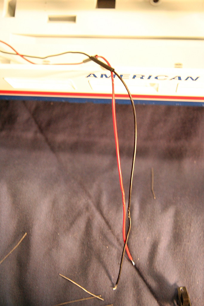
cut the pos and neg wires that run to the power transfer post that provides
power to the roof wiring. At the end of each of these four wires (that run
to the trucks) I added a single polyfuse to protect against shorts.
Source
for the fuses:
http://www.allelectronics.com/make-a-store/item/RXE-065/RESETTABLE-CIRCUIT-PROTECTOR-0.65-1.3-AMP/-/1.html
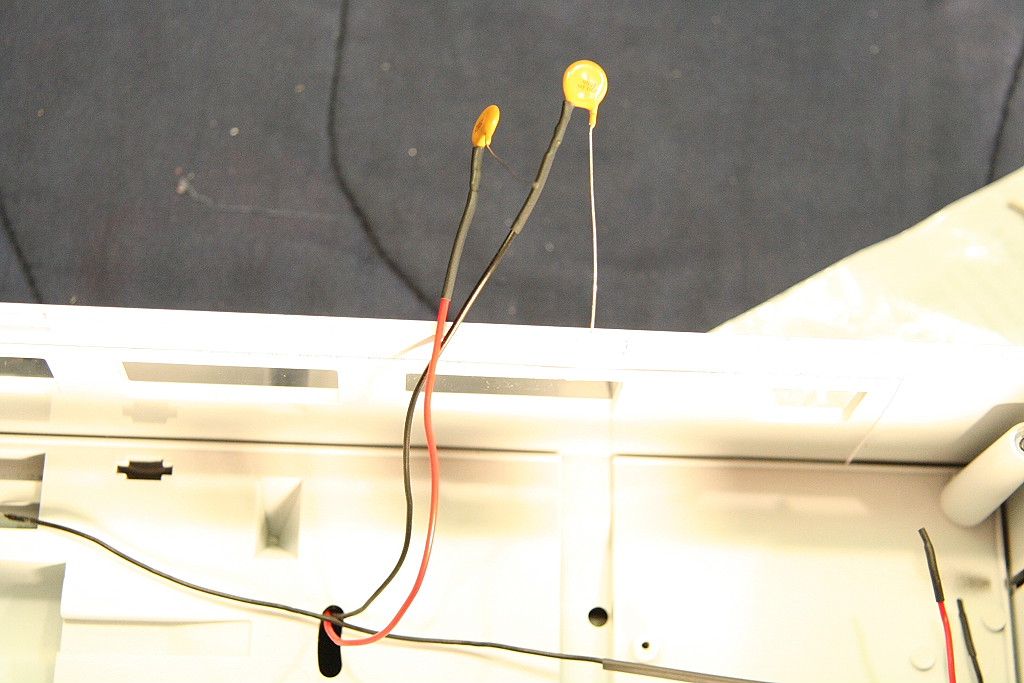
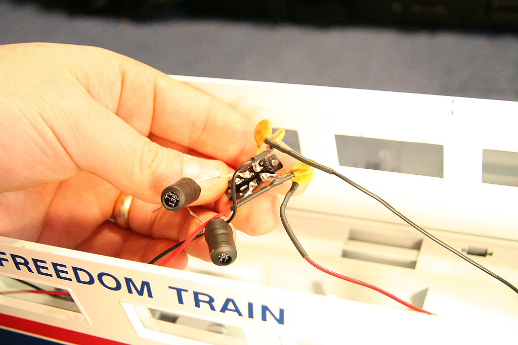
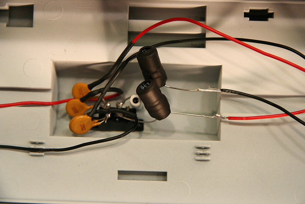
From there, I then added the selected the switch and added two
inductors (Choke Coils), one to each center post. (This is where the power
wires will be run to the overhead lights) (I added heat shrink to the
inductors.) The wires with the poly fuses are added to one side of the
switch terminals. (two per terminal - two left rail pickup wires on one
terminal and two right rail pickup wires on the other.
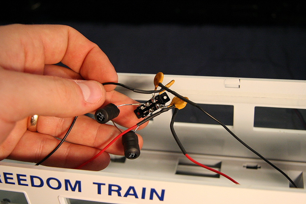
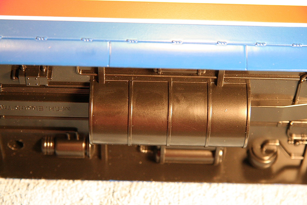
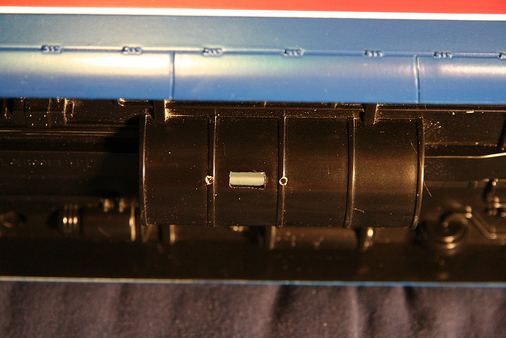
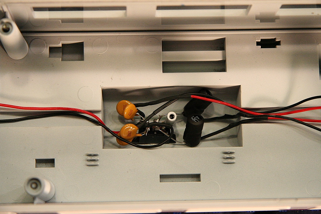
Next, I selected where I wanted the switch to be but still fit
the switch with inductors and polyfuses. The formed tank on the bottom of
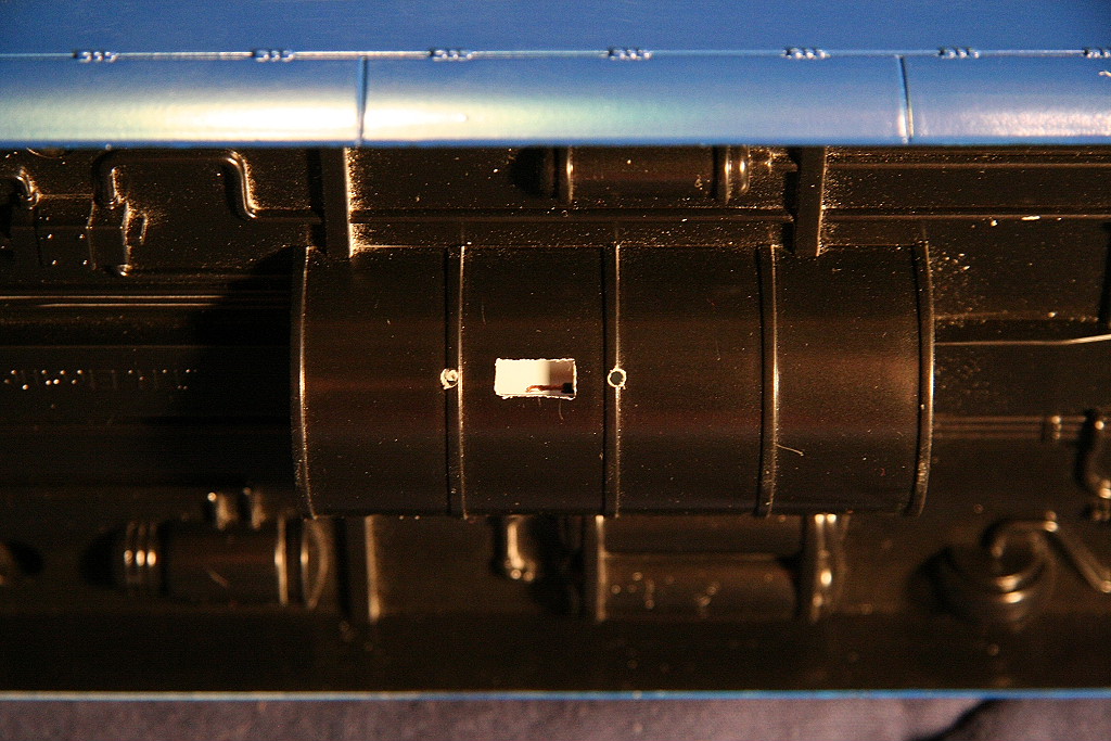
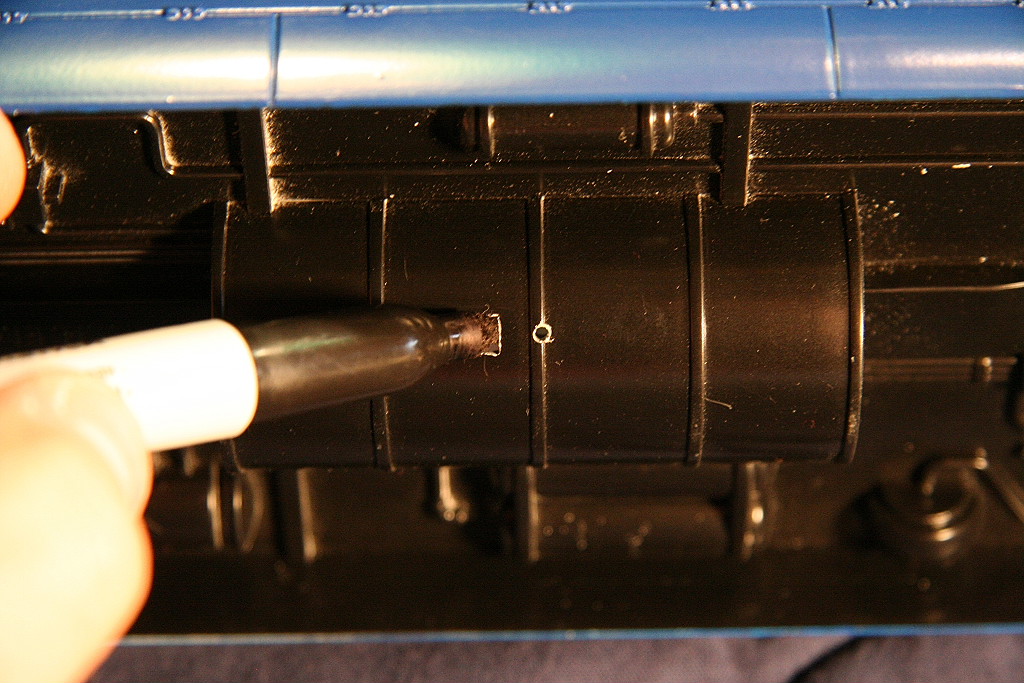
the car worked perfectly. I drilled out a slot for the switch head and the
screws.
When you're finished this is what it should look like.
Instructions for Observation Cars:
The first run observation cars did already come with light
switches. The only thing I wanted to add was inductors and polyfuses to
protect against shorts.
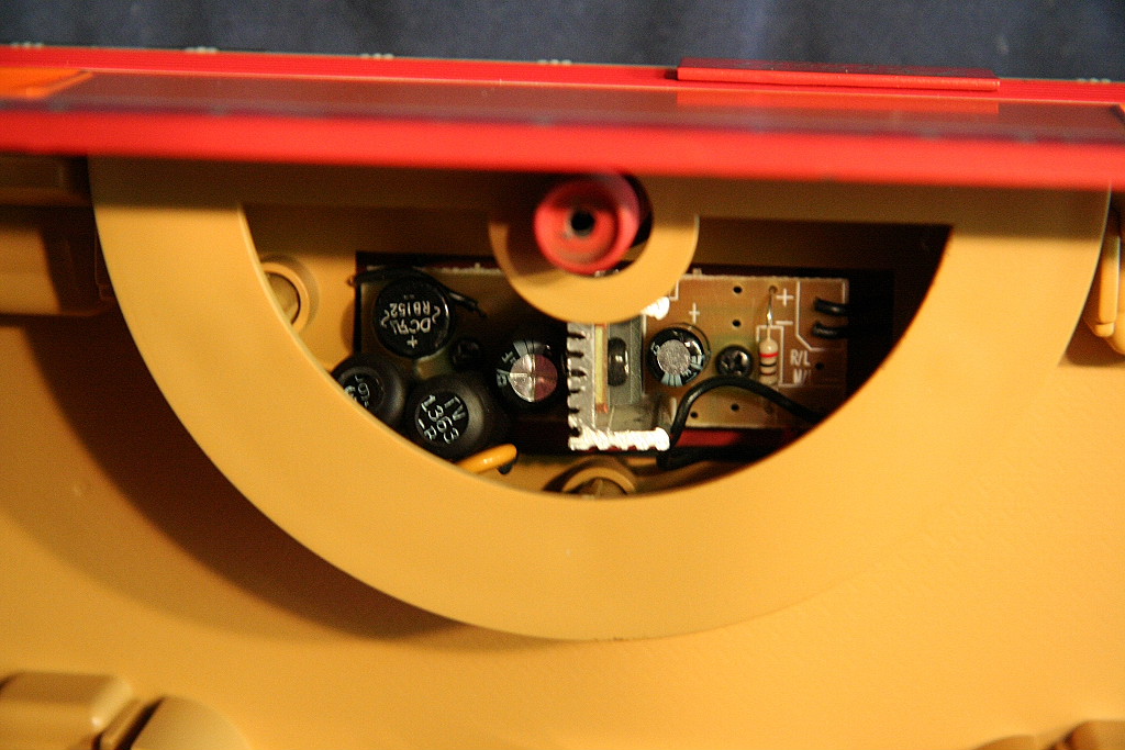
The voltage control board is located in the rounded bar area.
Once you remove the floor you can get access to it.
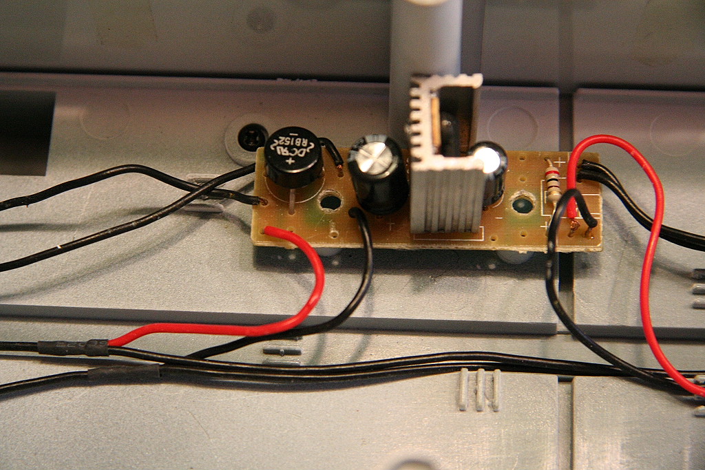
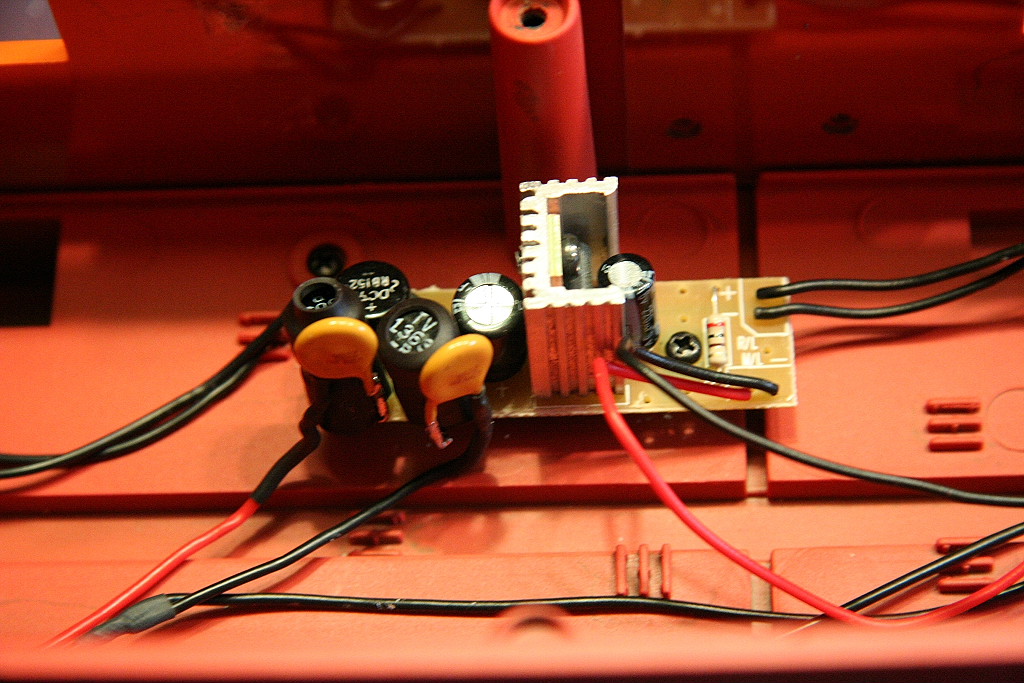
The red and black wires that run to the left bottom side of the
board are the power feeder wires to the board. I removed the wires from
the board and added one inductor to each location in the board. I then
added two polyfuses per wire end (only one each are pictured) and wired the
other end of the polyfuse to the inductor. I then reinstalled the board
and reassembled the car.
__________________________________________________________________________________
Return to Garden Railroad
Modification page.

Web Counter