MTH: Challenger Repair/Modifications
page:
(Click here for MTH; Challenger -
Photo & Video Page)

Model Info:
- MTH Product Pages:
- Clinchfield #673: (70-3004-1):
http://www.mthtrains.com/70-3004-1 (2001 model) (Announced
2001 v2 Catalog, Delivery=May 2004)
- Clinchfield #670: (70-3046-1):
http://www.mthtrains.com/70-3046-1 (2019/2020 model) (Announced
6/20/2019, Delivery=Production Cancelled)
- Delaware & Hudson #1535: (70-3013-1):
http://www.mthtrains.com/70-3013-1 (2004 model) (Announced
2004 Catalog, Delivery=2006)
- Denver Rio Grande #3710: (70-3014-1):
http://www.mthtrains.com/70-3014-1 (2004 model) (Announced
2004 Catalog, Delivery=2006)
- Denver Rio Grande #3801: (70-3047-1):
http://www.mthtrains.com/70-3047-1 (2019/2020 model) (Announced
6/20/2019, Delivery=Production Cancelled)
- Northern Pacific #5148: (70-3015-1):
http://www.mthtrains.com/70-3015-1 (2004 model) (Announced
2004 Catalog, Delivery=2006)
- Union Pacific #3967: (70-3002-1):
http://www.mthtrains.com/70-3002-1 (2001 model) (Announced
2001 v2 Catalog, Delivery=May 2004)
- Union Pacific #3977: (70-3003-1: Grey w/Silver):
http://www.mthtrains.com/70-3003-1 (2001 model) (Announced
2001 v2 Catalog, Delivery=May 2004)
- Union Pacific #3980: (70-3016-1: Grey w/Yellow):
http://www.mthtrains.com/70-3016-1 (2004 model) (Announced
2004 Catalog, Delivery=2006)
- Union Pacific #3985: (70-3043-1):
http://www.mthtrains.com/70-3043-1 (2019/2020 model) (Announced
6/20/2019, Delivery=Production Cancelled)
- Union Pacific #3978: (70-3044-1: Grey w/Silver):
http://www.mthtrains.com/70-3044-1 (2019/2020 model) (Announced
6/20/2019, Delivery=Production Cancelled)
- Union Pacific #3977: (70-3045-1: Grey w/Yellow):
http://www.mthtrains.com/70-3045-1 (2019/2020 model) (Announced
6/20/2019, Delivery=Production Cancelled)
- Western Maryland #1206: (70-3017-1):
http://www.mthtrains.com/70-3017-1 (2004 model) (Announced
2004 Catalog, Delivery=2006)
- Owners Manual:
Challenger-OwnersManual.pdf
(For all Challengers)
- PS2 Sound File: -
g013pf3chalengrall031223afin.mth
(For all Challengers)
- Parts Diagram:
Challenger_PartsDiagram.pdf
- Photos/Videos of model:
Challenger - Photos/Videos
Model Overview:
The Challenger is part of MTH's very first One Gauge steam offerings.
- Detail is excellent and true to prototype with key detail
parts being made of metal/brass
- Axles and gears are all metal for long life
- Plastic frames (both front and rear engine sets) with
plastic boiler and tender shell.
- Smoke output from both stacks timed to engine chuffs
- All metal connecting rods and running gear
________________________________________________________________________________
MTH Challenger Repair/Modifications:
Modifications/Topics list:
________________________________________________________________________________
08/01/04
MTH Challenger Smoke unit
not puffing fix:
If you are having issues with the smoke unit
not flowing air properly then you may have:
- Oil inside the fan chamber causing it to slow / bog down.
- The rubber gasket has swollen or shifted position and is now blocking
the air passage between the fan assembly and the fluid reservoir.
If you
have overfilled the smoke unit or have tipped the engine over with the unit
filled with smoke fluid and have fluid in the air chamber you can simply just
allow it to dry out over a period of time and it will return to normal
operation.
If the
rubber gasket is blocking the air passage, you may need to disassemble the smoke
unit to trim or reposition the gasket to eliminate the blockage.
Picture of the gasket:
________________________________________________________________________________
08/21/04
Tender plug problem & repair:
See this link:
Tender plug repair
__________________________________________________________________________________
09/4/14
Reduce
front driver wheel slippage:
To
reduce the slippage of the front engine set it requires additional weight be
applied to the wheels. To do this you need to add additional weight to the
front of the engine and add suspension springs to transfer that weight.
STEP 1:
Adding weight
Add between 1-3 lbs (depending on preference) in two
areas. (Use hot glue to adhere the weights in the boiler)
1. Inside the boiler on the sides near the front with the motor as the
center point (same amount of weight before and after). (Photos not
yet available)
2. To the front engine set near the front.
- Option 1: Add weight to the inside of the front engine set
(Not visible but harder to accomplish and requires some disassembly)
- Option 2: Add weight to the front of the pilot between the
front air pumps (will be visible)
Option 1:
Add weight to the inside of engine set:
- PHOTOS NOT YET AVAILABLE
Option 2:
Add weight to the front of the pilot between the front air pumps:
The photos below illustrate how it's done. (This adds about 7oz.)
STEP 2:
Add Suspension Springs:
Add springs in two locations:
1) Between the bottom of the boiler and front engine set
2) At the articulation hinge-pin at the back of the front engine set
Spring between boiler bottom and
front engine set:
The photos below explain the steps.
The plate is made from aluminum and obtained from Lowe's Hardware Store. The Spring is the
same one I used on the Big Boy pilot and is from Ace Hardware and is spring
#138(Item#18649).
Spring at the articulation
hinge-pin:
See the photos below. Use Ace Hardware spring
#182. You may want to experiment a bit with different spring types and
lengths to get the right amount of tension and allow for proper range of motion.
A metal washer was used to protect the plastic from the spring.
Final Step: Check wheel slippage with pull test
To test whether you have the right amount of weight in the right
locations and have the right spring tension, do a pull test by starting the
engine moving and hold the engine in place by holding the tender coupler and see which
set of drivers loose traction first. If you have the right balance
of weight and spring tension, both driver sets should start to slip at the same
time or close to it.
__________________________________________________________________________________
08/21/04
MTH Challenger front driver binding at slow speed fix:
If you see hesitation when running (usually at
slow speed) you may have an issue with connecting rods drilled slightly off center/out of spec on one of the
driver sets.
Driveline binding / not running smooth (MTH resolved these issues with their
Triplex and the 2015 production run of Big Boys.)
First best option is to try and replace side
rods on the affected engine set with others to see if this helps the situation.
You can also try shimming rod holes as noted
below. If you attempt to shim, an analysis will need to be done in order to
determine where the best placement is for any shims and this will come from
observing the drive set running slowly and where in the rotation it's binding.
**********************************
Shimming rod holes:
My solution was to purchase a package of brass sheets in various
thicknesses and use them to reduce the play between the connecting rods and the
connecting rod driver pin by making a spacer bushing. (Note:
This shim solution will likely only work if the rod holes aren't too far out of
spec. If they are too far out of spec, they will likely need to be
replaced.
Using scissors, cut a strip from the thickest sheet and looped
it to create a spacer bushing. Make sure the bushing isn't taller than
the width of the connecting rods. (Wrapping the strip around a properly
sized screw driver helps when trying to make it round.) Next, cut a strip of a medium
thickness sheet and looped it to create another spacer bushing. In
this case, a thicker spacer bushing was used on the: first driver left (fireman's) side, and both second
drivers. The second medium thickness bushing was added to both second
drivers. By adding the second medium thickness bushing, this made it so
there is very little slop between the connecting rods on the second drivers and
the connecting rod driver pins.
I found out that the second inner bushing was needed through much
trial and error and the fact there was still a lot of slop in the second driver
pin even after the first thick bushing was made.
Below is a picture of the two bushings combined before they were
inserted onto each of the second drivers. The thinner bushing is inside
the thicker one.
Next, insert the bushing into the connecting rod hole. In
this case, the single thick bushing.
Then fit the connecting rod onto the driver connecting rod driver
pin and press down on the connecting rod and the bushing with your thumb.
I jiggled the bushing and rods with my thumb until the bushing conformed to the
curvature of the connecting rod pin.
Repeat the above steps for both second drivers using the double bushing.
________________________________________________________________________________
09/19/04
MTH Challenger - G scale Kadee #830 coupler added to the
Tender:
Most of the individuals I've spoken to that
have added Kadee couplers to their Challenger tenders have used a #1 scale 820
or 821. I prefer the
larger G scale size over the #1 scale because they will be more likely to stay
coupled on poorly leveled and uneven
track and thus provide me a little more peace of mind.
After a little modifying, I was able to get the G scale 830
knuckle to attach to the existing MTH tender coupler arm. Here is what the tender
coupler looks like in it's original configuration. (except in these
example photos I went back and made for the site, I put the knuckle on the arm
upside down  , but you
get the idea.)
, but you
get the idea.)
I modified an 830 coupler like you see below. It required
cutting the end off, drilling a hole for the bolt and filing the entire top of
the arm to allow the coupler to be level with the tender. I also filed the
bottom of the arm at a slight angle to give the knuckle a slight incline so it
would be at the proper height. In addition, I dug out the parts you see
next to the coupler to use for the new assembly.
I then slid the new 830 onto the existing MTH tender coupler arm
and bolted it securely in place.
Next, I set the stock spring in place and reattached the arm to the
tender. I added a modified and polished washer to the pivot screw point to
add a little more stability to the arm so the coupler would have less up and
down play. The final screw was then put in place. I oiled the pivot
assembly and the ridge on the back tender wall where the coupler arm now rests
against it.
And as you can see, it was a success! It works better than before
and I now have a G scale Kadee on my tender ready to pull revenue runs.
________________________________________________________________________________
05/17/05
MTH Challenger/Big Boy - G scale Kadee #789 coupler added to the
Front:
The Challenger & Big Boy both come with a non-functioning #1
scale size coupler on the front. Not an issue unless you plan to do some
sort of lash-up behind another engine or consist.
After a bit of modifying I was able to install
a Kadee #789 on the front and eliminate the fake one.
Modifications:
Installed:
To accomplish this, you need to pull the pin holding the coupler
assembly in place. (from the bottom) It is very difficult to remove
and had to slowly work it out with a twisting motion.
Once out, the Kadee #789 can be modified with a dremel and a file
to drill a new hole and file it down so it fits through the front opening.
The Kadee uncoupler arm needs to be cut off smooth with the
bottom of the coupler.
One benefit from this modification is the coupler assembly is now
tight enough to keep from working it's way open after running the engine a
while.
________________________________________________________________________________
01/11/05
Challenger/Big Boy Drawbar upgrade:
I found that trying to back heavy, long trains
up a steep grade would put cause the factory drawbar to tip down
allowing the tender-drawbar peg to come out of the drawbar. To eliminate
this issue and also shorten the distance between the engine and tender I made
this custom drawbar out of scrap steel.
I replaced the stock spring with a few of the plastic washers
that were included in the Kadee 881 adapter package. By using the washers instead of a spring, they help hold the
drawbar in place when under heavy load backing up.
Here is the result.
Drill bit sizes used:
________________________________________________________________________________
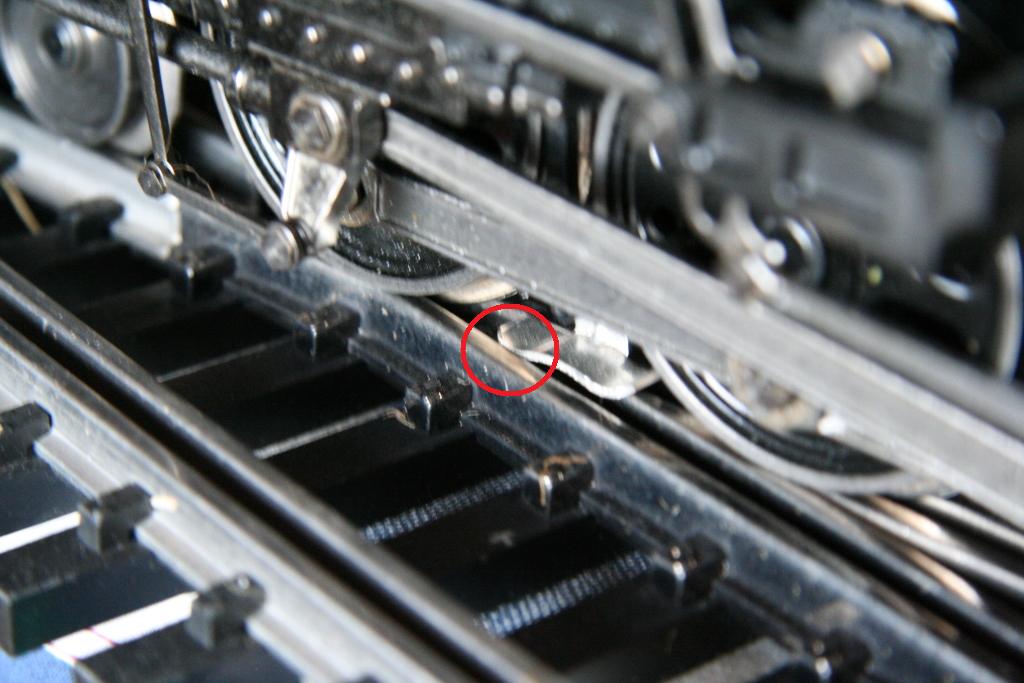
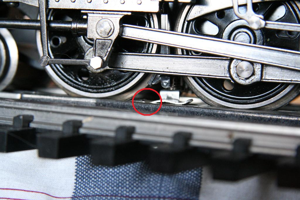
03/04/2009
Power Pickup Sliders getting caught in switch frogs
(Particularly #6 switches)
For those having problems with their engine having a slider that
dips in the frog which causes the engine get hung up or jerk, you will need to
modify the slider just a bit.
In some cases, the slider screw hole was not drilled perfectly
straight up and down. This results in the slider being tilted a bit front
to back. With the one end of the slider tilted down, that end will have a
tendency to drop in the frog as it passes over and get hung up.
The solution I came up with for this was to take and bend the
slider pad to compensate and ensure the slider sits level on the track.
I first check to see if the slider is level front to back.
(The one in the photo here is already level)
Based on which end is dipped down, I know which way to bend the
slider head to compensate.
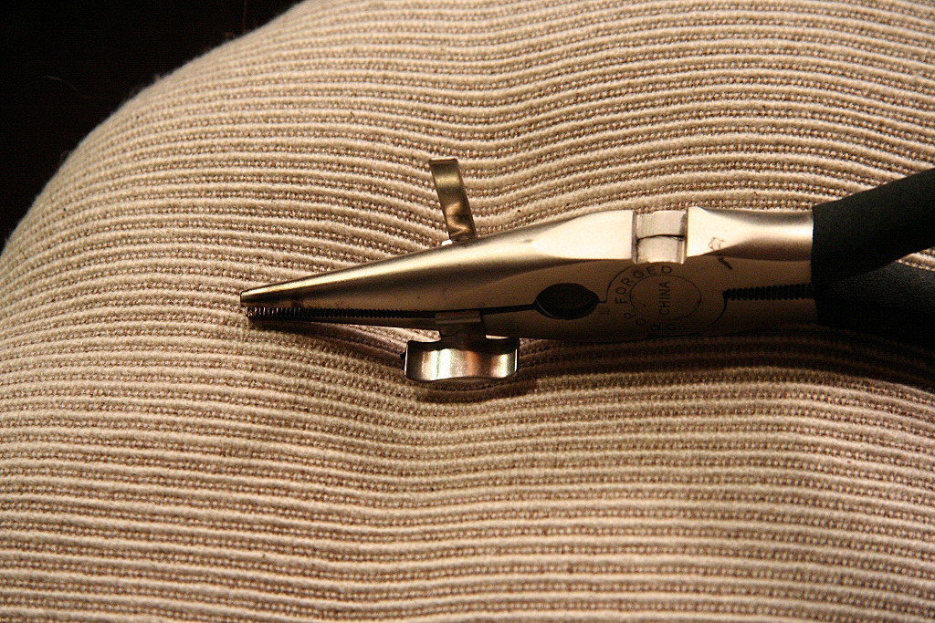
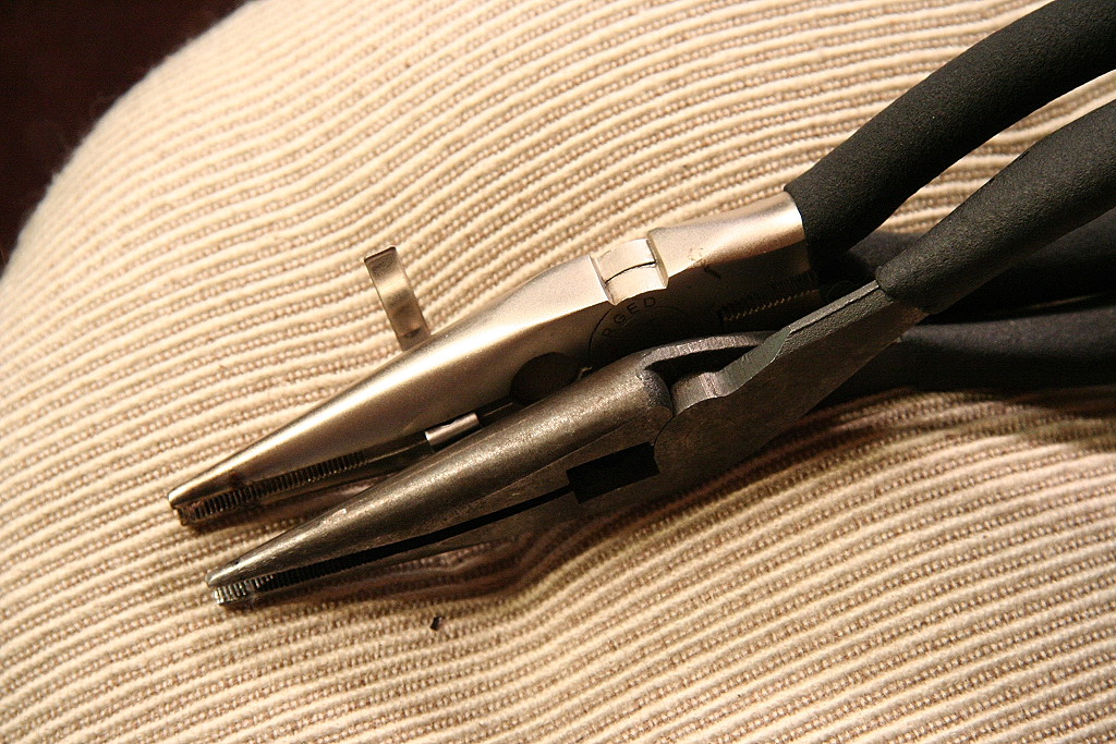
One way to fix is to take the slider off the engine and then use two pairs of pliers
to bend the slider shoe pad so it is oriented correctly against the rail.
After you bend, reinstall it and check. You may have to repeat these steps
a few times to get it just right. To speed this process you may be able to
bend the slider with it on the engine by hand.
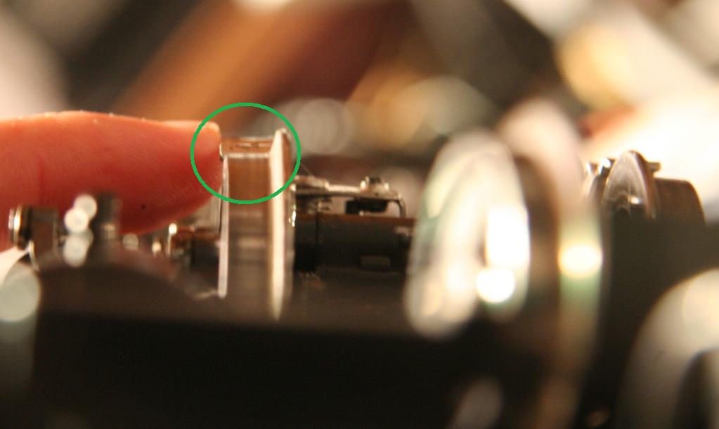
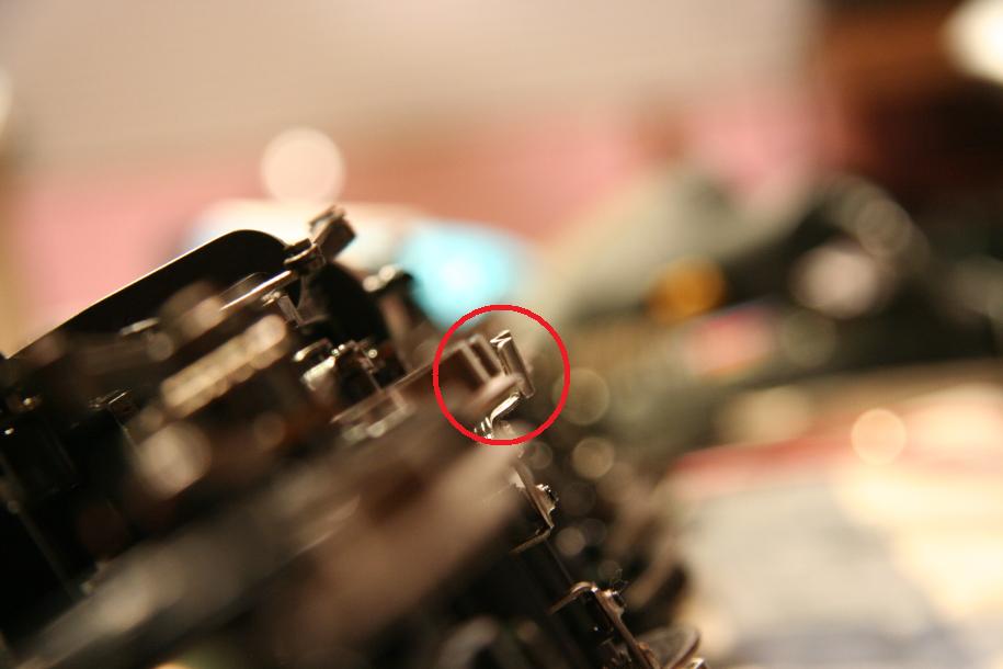
The other thing to check for is to make sure the outside edge of
the slider is level as well. If the outside end is dipped too far down it
can get caught as well. To tell if it's level, put the engine on it's side
and look down the bottom of the drivers and see how the slider looks in
comparison. The slider inner to outer level should match.
|
|

|
|
This is level
|
|

|
|
This isn't.
|
|
|
If you still have a slider getting caught in a #6 switch frog,
it's probably with the engine entering the main from the siding. (see
photos below) If this occurs, you will need to take (likely with a pair of
pliers) and bend the end of the slider that's dipping down in frog out just a
tad. So in this case below, the left side of the photo is the front of the
engine, you need to make the front end of the slider bend out further to the
left some. (Assuming the slider is already flat and level from the checks
above). Don't bend it too much and remember you are bending it out on the
horizontal axis, you want to keep it flat and level. Also, make sure
the slider screw is fairly secure in the hole you may need to tighten it down
some.
(Note: you may read where some have gone with the method of
bending the outside edge of the slider way up to prevent it from getting caught.
This is not necessary if you go through these steps noted above. If it's
getting caught it's just out of adjustment by likely just a little bit.)
Once you have your sliders set right they will work reliably from
then on, it's just a matter of getting any trouble sliders properly set which
really doesn't take too much time.
________________________________________________________________________________
08/21/04
Charging the engine's PS2 on-board battery:
See this link:
Charging engine PS2 battery
____________________________________________________________________________________________________________________
09/4/14
Polarity switch location:
All Protosound 2 Challengers do not have polarity switches.
A custom polarity switch can be installed and will post details at a later
point.
__________________________________________________________________________________
Return to Garden Railroad
Modification page.
Web Counter